Types of Machining Processes


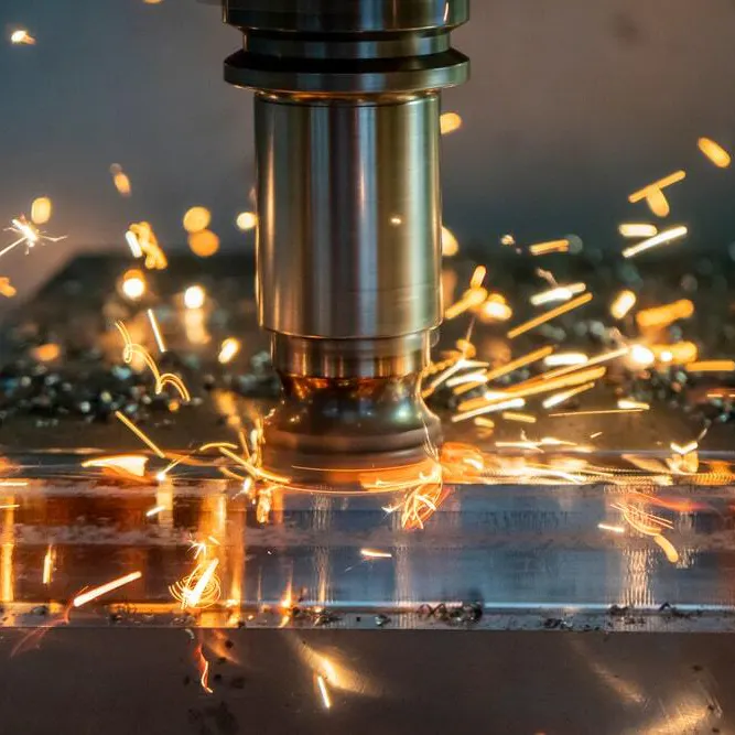
Types of machining processes refer to the range of subtractive manufacturing methods used to shape, cut, and finish raw materials into precise components. Types of machining processes cover a broad spectrum of operations, from turning and drilling to grinding and electrical discharge machining, each designed for specific materials, geometries, and tolerance requirements. Machinists select a process based on factors like material hardness, part complexity, surface finish requirements, and production volume. Industries ranging from aerospace to medical device manufacturing depend on the accuracy that machining delivers, with tolerances reaching as tight as ±0.0001" (±0.0025 mm) in high-precision applications.
Types of machining processes are categorized by the cutting action, tool type, and energy source involved in material removal. Mechanical processes (turning, milling, drilling, broaching) rely on physical cutting forces, while non-conventional processes (electrical discharge machining, electrochemical machining) use thermal or chemical energy to remove material. A single manufactured component frequently requires multiple machining operations in sequence to meet dimensional and surface finish specifications. The choice of process directly affects production cost, cycle time, and part quality, making process selection a foundational decision in any manufacturing workflow.
What Are the Types of Machining Process Tools?
The Types of Machining Process Tools are listed below.
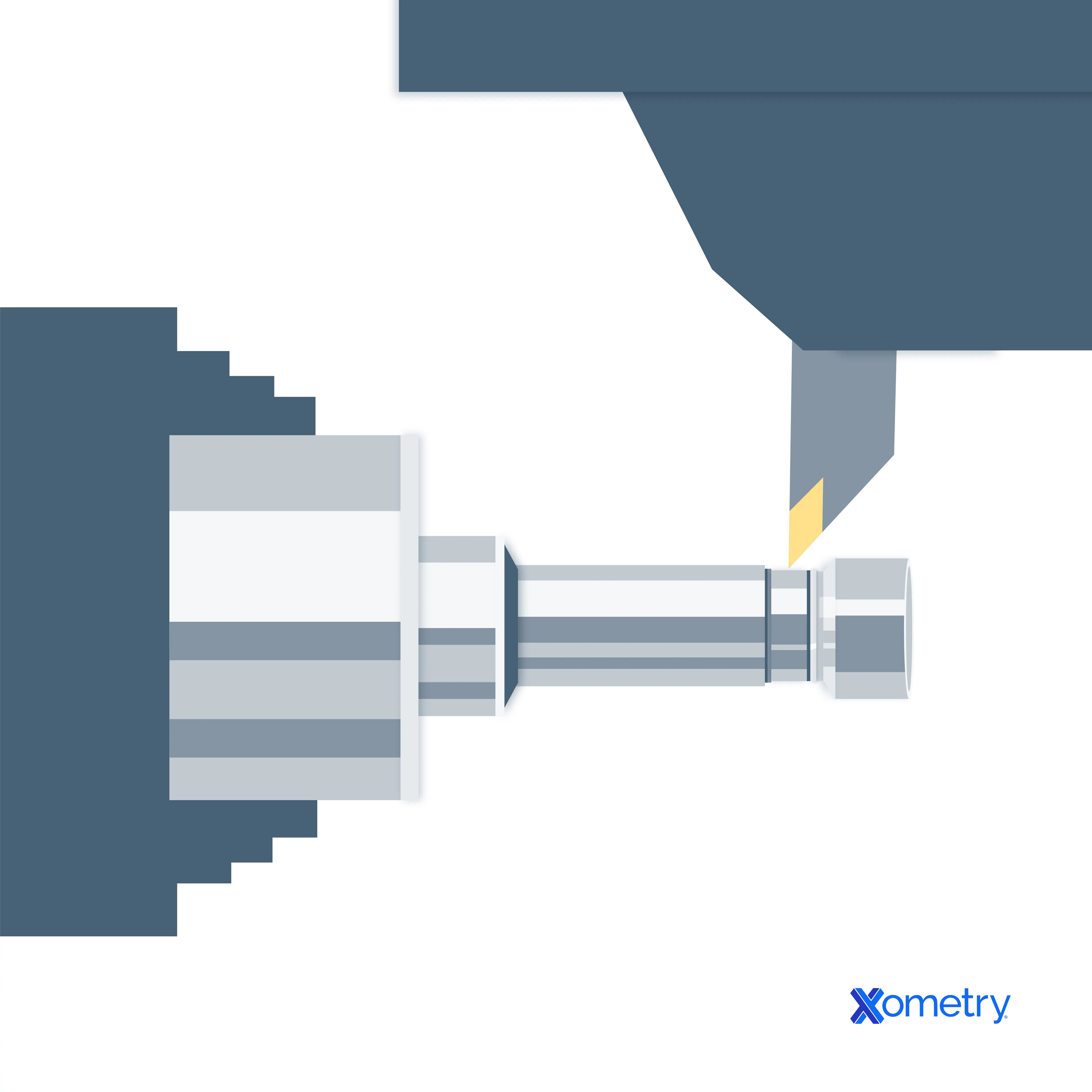
- Turning Tools: Turning tools are single-point cutting instruments mounted on a lathe to remove material from a rotating workpiece. The cutting edge contacts the workpiece at a controlled depth and feed rate, generating cylindrical, conical, or contoured profiles. Common geometries include roughing tools, finishing tools, and threading tools, with carbide-tipped inserts being the standard for most metals in turning and machining.
- Drilling Tools: Drilling tools are rotary cutting instruments designed to produce cylindrical holes in a workpiece. Twist drills are the most common type, available in diameters from 0.05 mm to over 150 mm, and are typically made from high-speed steel (HSS) or solid carbide. Specialized variants (spot drills, center drills, step drills) address specific depth and diameter requirements in CNC Drilling.
- End Milling: End milling tools are multi-flute rotary cutters used on milling machines to remove material along horizontal, vertical, or angular paths. Flute counts range from 2 to 8, with fewer flutes suited for softer materials and higher flute counts used for harder alloys. Square end mills, ball end mills, and corner radius end mills address different profiles and finish requirements in End Milling.
- Grinding Machine: A grinding machine uses an abrasive wheel rotating at high speed to remove small amounts of material and achieve tight tolerances and fine surface finishes. Surface grinders, cylindrical grinders, and centerless grinders each serve different workpiece geometries. Surface roughness values achievable with grinding range from Ra 0.025 µm to Ra 1.6 µm, making it the preferred finishing operation for hardened steel in a Grinding Machine.
- Planing: Planing tools use a single-point cutting tool that moves linearly across a stationary or reciprocating workpiece to produce flat surfaces. The process is applied to large workpieces where milling is impractical, and cutting speeds typically range from 6 m/min to 30 m/min. Planning is common in heavy equipment manufacturing and structural fabrication for flat-bed and guide-rail surfaces.
- Sawing: Sawing tools include band saws, circular saws, and hack saws, all used to cut raw stock into workable lengths or shapes. Band saws operate at blade speeds of 15 m/min to 90 m/min, depending on material, and blade tooth pitch is selected based on material thickness. Sawing is the primary stock-preparation step before more precise machining operations.
- Broaching: Broaching tools are multi-tooth linear or rotary cutters that progressively remove material in a single pass to produce internal or external profiles (keyways, splines, round holes, non-circular bores). Each successive tooth removes 0.025 mm to 0.1 mm of material, and the entire cut is completed in one stroke. Broaching delivers tolerances of ±0.005 mm and is widely used in automotive transmission and firearm manufacturing.
- Electric Discharge Machining: Electric discharge machining (EDM) removes material through controlled electrical spark erosion between an electrode and a conductive workpiece submerged in dielectric fluid. Spark gap distances range from 0.01 mm to 0.5 mm, and material removal rates depend on pulse frequency and current. The process machines hardened steels, tungsten carbide, and exotic alloys that are difficult to cut mechanically, as detailed in Electrical Discharge Machining.
- Electrochemical Machining: Electrochemical machining (ECM) removes material through an anodic dissolution reaction driven by direct electrical current passed through an electrolyte solution (sodium chloride or sodium nitrate) flowing from 5 L/min to 30 L/min. The tool (cathode) never contacts the workpiece (anode), eliminating cutting forces and tool wear entirely. The process produces complex, burr-free geometries in conductive hard or heat-sensitive alloys used in turbine blade and medical implant production, as covered in Electrochemical machining.
1. Turning Tools
Machinists use turning tools on a lathe to remove material from a rotating workpiece. The cutting tool stays rigid while the part spins at a controlled speed. Single-point tools shape outer diameters, inner bores, grooves, and threads. Carbide, ceramic, and coated inserts resist heat and wear during high-speed cutting. Tool geometry, such as rake angle and nose radius, controls chip flow and surface finish. Coolant reduces heat and improves tool life during heavy cuts. Shops rely on turning tools for shafts, bushings, threaded rods, and precision cylindrical parts in automotive and aerospace work.
2. Drilling Tools
Drilling tools create round holes by rotating a drill bit into solid material. The tool feeds straight along its axis while the cutting edges at the tip remove material. Twist drills include flutes that carry chips away from the hole. Step drills, spade drills, and gun drills handle different hole sizes and depths. Cutting speed, feed rate, and lubrication affect hole accuracy and surface quality. Peck drilling clears chips during deep-hole operations. Production lines use drilling tools for bolt holes, fluid passages, and alignment features in engine blocks and structural assemblies.
"Effective process optimization begins with the integration of DFM principles during the initial design phase to mitigate material fatigue and ensure dimensional stability. Designers must synchronize GD&T specifications with the specific kinematics of the selected machining process (such as 5-axis milling or precision grinding) to eliminate secondary operations and reduce total cycle time."
3. End Milling
End milling removes material with a rotating cutter that has multiple cutting edges. The tool moves across the workpiece in several directions to shape slots, pockets, and complex surfaces. Flat end mills create sharp edges and flat bottoms, while ball end mills generate curved profiles. Roughing end mills remove large volumes of material with reduced cutting force. CNC machines control tool paths with high precision for intricate designs. Tool coatings extend life and reduce friction. Industries use end milling for molds, dies, brackets, and precision machine parts.
4. Grinding Machine
Grinding machines remove very small amounts of material using abrasive grains bonded into a wheel. The wheel rotates at high speed and cuts through microscopic chips. Surface grinders produce flat finishes, while cylindrical grinders handle round components. Centerless grinding supports high-volume production of shafts without using centers. Abrasive selection depends on material hardness and finish requirements. Dressing the wheel restores cutting ability and accuracy. Precision industries use grinding machine for bearings, cutting tools, and hardened components that require tight tolerances and smooth finishes.
5. Planing
Planing machines move a workpiece in a straight back-and-forth motion under a fixed cutting tool. The tool removes material in linear strokes across large flat surfaces. Heavy-duty frames support large and rigid parts during machining. Operators adjust stroke length, feed rate, and depth of cut to control material removal. The process handles wide surfaces that exceed standard milling capacity. Workshops use planing for machine beds, structural bases, and long guideways where flatness and alignment matter.
6. Sawing
Sawing cuts raw material into smaller sections using a toothed blade. The blade moves in a continuous loop or reciprocating motion depending on the machine type. Band saws cut curves and thick materials, while circular saws deliver straight and fast cuts. Blade material and tooth pitch affect cutting efficiency and finish. Coolant reduces heat and extends blade life during heavy cutting. Fabrication shops use sawing to size bars, pipes, and plates before further machining steps.
7. Broaching
Broaching removes material with a long tool that carries multiple teeth arranged in sequence. Each tooth cuts slightly deeper than the previous one until the final shape forms in a single pass. Internal broaching produces keyways, splines, and polygonal holes. External broaching shapes flat or contoured surfaces. The process delivers high accuracy and repeatability in mass production. Tool design determines the final profile and cutting load. Manufacturers use broaching for gears, firearm components, and precision fittings.
8. Electric Discharge Machining
Electric discharge machining removes conductive material through controlled spark erosion between an electrode and the workpiece. The process uses electrical discharges to vaporize small portions of material. No mechanical cutting force acts on the part, which suits very hard or delicate materials. Die-sinking EDM creates cavities, while wire EDM slices through material with a thin wire. Dielectric fluid cools the area and removes debris. Toolmakers use electric discharge machining for molds, dies, and intricate shapes that conventional tools struggle to produce.
9. Electrochemical Machining
Electrochemical machining removes material from a conductive workpiece by passing an electric current through an electrolyte between a tool and the part. The workpiece dissolves at the atomic level in a controlled manner. No heat-affected zone or mechanical stress forms during the process. Complex shapes and thin sections maintain high accuracy without tool wear. Electrolyte flow carries away dissolved material and keeps the process stable. Aerospace and medical industries rely on electrochemical machining for turbine blades, surgical instruments, and components with tight tolerances and smooth surfaces.

What Is Machining?
Machining is a subtractive manufacturing process in which material is removed from a solid workpiece using cutting tools, abrasives, or energy-based methods to produce a part with defined dimensions, geometry, and surface finish. The process starts with a raw block, bar, or casting and progressively removes excess material until the part conforms to engineering specifications. Dimensional tolerances in machining range from ±0.5 mm in rough operations to ±0.001 mm in precision grinding and EDM finishing. Cutting speeds, feed rates, and depth of cut are the three primary variables that control material removal rate and surface quality. Metals (aluminum, steel, titanium), polymers (nylon, PEEK), and some ceramics are all machinable, with tool selection driven by material hardness and thermal properties. The process is central to producing components for aerospace, automotive, medical, and defense sectors, where geometric accuracy and repeatability are non-negotiable manufacturing requirements.
What Industries Rely Most Heavily on Machining Today?
Industries Rely Most Heavily on Machining Today are listed below.
- Aerospace Industry: The aerospace industry relies on machining to produce airframe structures, engine components, and landing gear parts to tolerances as tight as ±0.005 mm. Titanium alloys and aluminum 7075-T6 are the primary materials machined for flight-critical parts. A case study from turbine blade production shows that 5-axis CNC milling reduces setup time by 40% compared to sequential 3-axis operations.
- Automotive Industry: The automotive industry uses machining for engine blocks, crankshafts, transmission housings, and brake components, with production volumes reaching millions of units annually. Cylinder bore tolerances are held to within ±0.01 mm to ensure proper piston fit and combustion efficiency. Transfer lines with dedicated CNC stations are a standard configuration in high-volume powertrain plants.
- Medical Device Industry: The medical device industry machines surgical implants, orthopedic components, and instrument bodies from biocompatible materials (titanium Grade 5, stainless steel 316L, PEEK). Bone screw threads are machined to ISO 5835 standards with surface roughness values below Ra 0.8 µm to promote osseointegration. Clean-room compatible CNC machining centers are used to meet FDA and ISO 13485 regulatory requirements.
- Defense and Firearms Industry: Defense manufacturing depends on machining for weapon components, armored vehicle parts, and guidance system housings, where material integrity and dimensional accuracy directly affect performance. Firearm receiver machining tolerances are typically held to ±0.025 mm for reliable function. Broaching and EDM are standard processes for producing rifling, spline-bored components, and precision housings.
- Oil and Gas Industry: The oil and gas industry machines downhole tools, valve bodies, and pressure vessel components from high-strength alloys (Inconel, 4140 steel, duplex stainless steel) rated for pressures exceeding 15,000 psi. Thread forms on drill collars and casing connectors are machined to API 5CT and API 7-2 standards. CNC turning centers with live tooling are the primary equipment in oilfield component shops.
- Electronics and Semiconductor Industry: The electronics industry machines heat sinks, enclosures, connector bodies, and semiconductor tooling from aluminum, copper, and engineering plastics. Micro-machining produces features as small as 50 µm for sensor housings and optical mounts. High-speed machining centers operating at spindle speeds above 30,000 RPM are standard for fine-detail aluminum components.
Can Machining Produce Precision Parts?
Yes, machining can produce precision parts. Subtractive processes deliver dimensional tolerances from ±0.001 mm in precision grinding and EDM to ±0.025 mm in standard CNC milling, making them among the tightest tolerances achievable in manufacturing. CNC turning centers hold cylindricity values between 0.010 mm and 0.020 mm on shaft diameters up to 500 mm, and surface roughness values of Ra 0.2 µm are routinely achieved in finish grinding operations. Coordinate Measuring Machines (CMMs) verify part conformance to GD&T callouts, with measurement uncertainty as low as 0.5 µm on high-end metrology systems. In the aerospace sector, turbine disk bores machined from nickel superalloys meet roundness specifications within 0.003 mm to ensure rotor balance at operating speeds exceeding 10,000 RPM. Medical implants machined from titanium Grade 5 meet ASTM F136 dimensional standards with thread pitch errors below 0.005 mm. Precision machining is the accepted production method for applications where dimensional variation directly affects structural safety, mechanical fit, or regulatory compliance.
What Is the Purpose of Machining?
The purpose of machining is to remove excess material from a workpiece to produce a part that conforms to specified dimensions, surface finish, and geometric tolerances required for functional assembly or end use. Raw material stock (billets, castings, forgings) arrives in near-net shapes that lack the precision needed for mechanical assembly, and machining bridges the gap from rough form to finished dimension. Tolerances of ±0.001 mm to ±0.1 mm are achievable depending on the process selected, and surface finish values from Ra 0.025 µm (precision grinding) to Ra 3.2 µm (rough turning) address the full range of functional surface requirements. Machining produces mating features (bores, threads, slots, keyways) that allow components to fit, move, and transfer load as designed. The process extends to corrective operations where cast or forged parts require post-processing to remove flash, improve concentricity, or establish reference datums. Without machining, mass-produced interchangeable parts would be unachievable, as the interchangeability of components depends on dimensional consistency that casting and forming alone cannot guarantee.
How Does Machining Contribute to Cost Efficiency in Manufacturing?
Machining contributes to cost efficiency in manufacturing by following the five steps below.
- Near-Net-Shape Machining. Near-net-shape starting material reduces the volume of metal removed, cutting raw material costs by 15% to 35% on complex aerospace forgings compared to machining from solid billet. Forged or cast preforms place material only where the final geometry requires it. The reduction in cutting time directly lowers machine-hour costs and tool consumption.
- High-Speed Machining (HSM). High-speed machining increases cutting speeds by 300% to 500% above conventional rates, reducing cycle times for aluminum aerospace components from hours to minutes. Spindle speeds above 20,000 RPM and feed rates above 10,000 mm/min are standard in HSM centers used for thin-walled aircraft structures. Lower cutting forces in HSM reduce workpiece deflection, producing better dimensional accuracy with fewer finishing passes.
- Toolpath Optimization. Optimized CNC toolpaths reduce air-cutting time (non-cutting motion) by 20% to 40% on complex 5-axis parts through adaptive clearing and trochoidal milling strategies. CAM software calculates constant chip-load toolpaths that extend tool life by 50% to 80% compared to conventional constant-depth passes. Fewer tool changes reduce downtime and per-part tooling costs.
- Multi-Operation Machining Centers. Turn-mill centers and 5-axis machining centers complete multiple operations (turning, milling, drilling, threading) in a single setup, eliminating re-fixturing time that accounts for 30% to 50% of total production time on complex parts. Single-setup machining improves positional accuracy from ±0.05 mm (multi-setup) to ±0.01 mm (single-setup) by removing datum transfer errors. Reduced handling also lowers the risk of part damage between operations.
- Scrap Reduction through Process Control. Statistical process control (SPC) applied to CNC machining lines reduces scrap rates from 5% to 10% down to below 1% by monitoring tool wear, spindle load, and dimensional feedback in real time. In-process gauging systems measure critical dimensions during the machining cycle and adjust offsets automatically. Scrap reduction at a production rate of 10,000 parts per month at [$50] per part saves [$20,000] to [$45,000] monthly compared to uncontrolled processes.
Can Machining Improve Material Properties Besides Shaping?
Machining improves material properties beyond shaping. The cutting process induces work hardening in the surface layer of ductile metals, increasing surface hardness by 10% to 30% in stainless steel and austenitic alloys due to plastic deformation from the cutting tool. Hard turning of bearing races produces a compressive residual stress layer 10 µm to 50 µm deep that extends fatigue life by up to 40% compared to ground surfaces without residual stress management. Surface finish improvements from machining directly affect tribological performance: reducing surface roughness from Ra 1.6 µm to Ra 0.4 µm on a shaft bearing surface decreases the friction coefficient by 15% to 25%, reducing wear rate and extending service life. Burnishing, a non-cutting machining operation, plastically deforms surface asperities to produce Ra values below 0.1 µm and introduces compressive stresses that improve corrosion resistance in aerospace aluminum components. Shot peening is sometimes integrated into post-machining sequences to extend the fatigue life of landing gear and turbine disk components by 20% to 60%.
What Materials Can Be Machined?
The materials that can be machined are listed below.
- Aluminum Metal: Aluminum is a lightweight, non-ferrous metal with a density of 2.7 g/cm³ and a machinability rating of approximately 300% to 1,500% relative to AISI 1212 steel, depending on alloy grade.
- Steel Metal: Steel is an iron-carbon alloy with carbon content ranging from 0.05% to 2.0%, machined in grades from free-machining 1215 steel (machinability rating 136%) to alloy steels like 4340 (machinability rating 45%).
- Stainless Steel: Stainless steel contains a minimum of 10.5% chromium, which forms a passive oxide layer that increases work hardening during machining and requires carbide or ceramic cutting tools.
- Titanium Metal: Titanium alloys have a low thermal conductivity of 6.7 W/m·K (Grade 5, Ti-6Al-4V), causing heat to concentrate at the cutting edge and requiring low cutting speeds of 30 m/min to 150 m/min.
- Nylon Polymer: Nylon is a semi-crystalline thermoplastic with a tensile strength of 70 MPa to 85 MPa, machinable with sharp HSS or carbide tools at cutting speeds of 100 m/min to 300 m/min.
- Fiberglass Material: Fiberglass is a composite of glass fiber and polymer resin, machined with diamond or carbide-tipped tools due to the abrasive nature of glass fibers, which causes rapid tool wear at rates 5 to 10 times higher than aluminum.
- Carbon Fiber: Carbon fiber reinforced polymer (CFRP) has a tensile strength of 500 MPa to 1,500 MPa and is machined with polycrystalline diamond (PCD) tools to prevent delamination and fiber pullout.
- Wood Material: Wood is a natural orthotropic material machined with high-speed router bits and saw blades at spindle speeds of 12,000 RPM to 24,000 RPM for furniture, cabinetry, and pattern-making applications.
- Ceramic Material: Ceramics are hard, brittle materials with hardness values of 1,200 HV to 2,500 HV, machined by grinding, ultrasonic machining, or laser processing rather than conventional cutting, as detailed in Ceramic resources.
Aluminum Metal
Aluminum is a non-ferrous, lightweight metal with a density of 2.7 g/cm³, roughly one-third that of steel, and a machinability rating of 300% to 1,500% relative to AISI 1212 steel depending on alloy and temper. Alloy 6061-T6 is the most widely machined grade, offering a tensile strength of 310 MPa, yield strength of 276 MPa, and a machinability rating near 900%. Alloy 7075-T6 delivers a tensile strength of 572 MPa for aerospace structural components and is machined at cutting speeds of 300 m/min to 600 m/min with carbide tooling. Alloy 2024-T4 is preferred for aircraft skin and bulkhead applications, with fatigue strength reaching 138 MPa at 500 million cycles. Free-machining alloy 2011-T3 contains lead and bismuth additives that produce short, brittle chips and enable drilling and turning at speeds up to 1,200 m/min. The thermal conductivity of aluminum at 167 W/m·K to 210 W/m·K dissipates cutting heat efficiently, reducing tool wear compared to titanium or stainless steel. Surface roughness of Ra 0.4 µm to Ra 1.6 µm is achievable in finish milling with diamond-coated or uncoated carbide inserts, making aluminum suitable for optical mounts, heat sinks, and structural airframe parts covered under Aluminum metal.
Steel Metal
Steel is an iron-carbon alloy with carbon content from 0.05% (low-carbon 1010) to 2.0% (high-carbon 1095), and its machinability varies from a rating of 136% for free-machining 1215 steel to 45% for alloy steel 4340. Low-carbon steels (AISI 1018, 1020) machine readily at cutting speeds of 100 m/min to 200 m/min with HSS or carbide tools, producing long, continuous chips that require chip breakers. Medium-carbon steels (AISI 1045, 4140) offer tensile strengths of 570 MPa to 1,000 MPa and are used for shafts, gears, and structural fasteners machined at 80 m/min to 150 m/min. High-carbon and alloy steels (AISI 52100, D2 tool steel) reach hardness values of 60 HRC to 65 HRC and require CBN (cubic boron nitride) or ceramic inserts for hard turning operations. Tool steel H13 is machined in the annealed condition (180 HB to 225 HB) before heat treatment to avoid excessive tool wear. Cutting fluid selection directly affects tool life: water-soluble emulsions at 5% to 10% concentration are standard for steel turning, extending insert life by 30% to 50% compared to dry cutting. The broad machinability range of steel grades is detailed further in the resources on Steel metal.
Stainless Steel
Stainless steel is an iron-based alloy containing a minimum of 10.5% chromium by weight, which creates a self-repairing passive oxide layer that provides corrosion resistance but increases work hardening during machining. Austenitic grades (304, 316L) have a work hardening rate 3 to 4 times higher than carbon steel, requiring sharp cutting edges, positive rake angles of 5° to 15°, and continuous cuts to avoid built-up edge. Martensitic grade 416 (free-machining stainless) achieves a machinability rating of 85% due to sulfur additions, and is machined at 90 m/min to 150 m/min with carbide inserts for valve stems and pump shafts. Duplex stainless steel (2205) combines austenitic and ferritic microstructures with a yield strength of 450 MPa, requiring cutting speeds of 50 m/min to 100 m/min to manage the high cutting forces generated. Surface roughness of Ra 0.4 µm to Ra 0.8 µm is achievable in finish turning 316L for medical implants and food-processing equipment. Grade 316L is the dominant stainless grade in surgical implant machining due to its biocompatibility and corrosion resistance in chloride environments, as covered under Stainless Steel.
Titanium Metal
Titanium alloys are characterized by a high strength-to-weight ratio, low density of 4.5 g/cm³, and extremely low thermal conductivity of 6.7 W/m·K for Ti-6Al-4V (Grade 5), which concentrates heat at the cutting edge during machining. Grade 5 (Ti-6Al-4V) is the most widely machined titanium alloy, with a tensile strength of 950 MPa to 1,100 MPa, and is machined at conservative cutting speeds of 30 m/min to 60 m/min to prevent premature tool failure from thermal softening. Grade 2 (commercially pure) is softer (tensile strength 345 MPa) and machines at up to 90 m/min, producing gummy chips that require high positive rake angles and sharp edges. Flood coolant applied at 20 L/min to 40 L/min is necessary for titanium machining to control cutting zone temperatures below 550°C, above which titanium reacts with tool materials and causes rapid notch wear. Tool life in titanium machining with uncoated carbide inserts is typically 5 to 15 minutes per edge, compared to 30 to 60 minutes for steel under equivalent conditions. The combination of high strength, low weight, and biocompatibility makes titanium the primary choice for aerospace fasteners, turbine blades, and orthopedic implants, as outlined in resources on Titanium metal.
Nylon Polymer
Nylon is a semi-crystalline thermoplastic polyamide with a tensile strength of 70 MPa to 85 MPa for unfilled nylon 6 and nylon 6/6, machined with sharp, polished HSS or uncoated carbide tools to minimize heat generation and surface smearing. The material absorbs moisture from ambient humidity at rates of 2.5% to 8.5% by weight, depending on grade, which affects dimensional stability during machining and requires moisture stabilization to the intended service environment before precision operations. . Cutting speeds for nylon range from 100 m/min to 300 m/min, with dry machining preferred to avoid moisture absorption from water-based coolants that cause part swelling. Nylon 6/6 is the most commonly machined grade for gears, bushings, and bearing cages due to its self-lubricating properties and wear resistance. Glass-filled nylon (30% GF) has a tensile strength of 175 MPa but is abrasive to cutting tools, reducing insert life by 40% to 60% compared to unfilled grades. Dimensional tolerances of ±0.05 mm to ±0.1 mm are practical for nylon machining due to thermal expansion (80 × 10⁻⁶/°C) and moisture sensitivity, and the range of nylon grades suited for machining is detailed under Nylon Polymer.
Fiberglass Material
Fiberglass is a composite material consisting of glass fiber reinforcement (E-glass, S-glass) embedded in a polymer matrix (polyester, epoxy, vinyl ester), with tensile strengths ranging from 310 MPa (chopped strand mat) to 1,700 MPa (unidirectional woven fabric). The abrasive nature of glass fibers causes tool wear rates 5 to 10 times higher than those experienced when machining aluminum, requiring diamond-coated (PCD) or solid carbide tools for cost-effective production. Cutting speeds for fiberglass milling range from 60 m/min to 300 m/min with PCD tooling to minimize heat buildup in the resin matrix, which softens above 120°C to 180°C depending on the cure system. Delamination and fiber pullout are the primary failure modes in fiberglass machining, controlled by using sharp tools, high spindle speeds, and low feed rates of 0.02 mm/tooth to 0.05 mm/tooth. Water jet cutting is an alternative for fiberglass sheet stock where delamination risk is high with rotary tooling. Fiberglass panels for marine, electrical insulation, and structural applications are machined to dimensional tolerances of ±0.1 mm to ±0.25 mm, as described in Fiberglass material resources.
Carbon Fiber
Carbon fiber reinforced polymer (CFRP) consists of carbon fiber reinforcement (tensile strength 3,500 MPa to 7,000 MPa per fiber) in an epoxy or thermoplastic matrix, producing a composite with specific strength exceeding titanium at a density of 1.6 g/cm³. Machining CFRP requires polycrystalline diamond (PCD) or diamond-coated carbide tools because the carbon fibers are abrasive enough to wear standard carbide tools within 2 to 5 minutes of cutting time. Trimming and drilling are the primary CFRP machining operations, with drilling spindle speeds of 3,000 RPM to 12,000 RPM and feed rates of 0.025 mm/rev to 0.075 mm/rev to prevent delamination at the entry and exit of the hole. Dry machining is standard for CFRP because water-based coolants introduce moisture that degrades the epoxy matrix over time. Fiber orientation relative to the cutting direction affects surface quality: cutting parallel to fibers produces smooth surfaces, while cutting perpendicular causes fiber pullout and fraying. Dust extraction rated to capture particles below 1 µm is required during CFRP machining due to respiratory hazards from airborne carbon fiber particles, and machining design details are covered under Carbon Fiber resources.
Wood Material
Wood is a natural, anisotropic material with mechanical properties varying significantly from grain direction: tensile strength parallel to grain ranges from 40 MPa to 120 MPa (pine to oak), while perpendicular-to-grain strength is 3 to 10 times lower. CNC router machining of wood uses spindle speeds of 12,000 RPM to 24,000 RPM with carbide-tipped or high-speed steel router bits, producing surface finishes of Ra 3.2 µm to Ra 12.5 µm depending on material density and grain orientation. Feed rates for wood CNC routing range from 2,000 mm/min to 8,000 mm/min, adjusted for wood species hardness and part geometry. Hardwoods (oak, maple, walnut) require sharper cutting edges and lower feed rates than softwoods (pine, cedar) to prevent grain tear-out. Moisture content directly affects dimensional stability during machining: wood at 8% to 12% moisture content is the standard range for furniture and cabinetry production to minimize post-machining warping. MDF (medium-density fiberboard) and plywood are the most dimensionally consistent wood materials for CNC machining, with MDF specifically offering a homogeneous composition, holding tolerances of ±0.1 mm to ±0.25 mm on flat profiles.
Ceramic Material
Ceramics are inorganic, non-metallic materials with hardness values of 1,200 HV to 2,500 HV (alumina to silicon carbide), making them resistant to conventional cutting tool materials and requiring specialized machining methods. Diamond grinding is the primary machining process for ceramics, using resin-bonded or metal-bonded diamond wheels at grinding speeds of 20 m/s to 60 m/s and material removal rates of 0.1 mm³/s to 10 mm³/s. Alumina (Al₂O₃) is the most widely machined ceramic, used for electrical insulators, wear-resistant liners, and biomedical implants, with bending strength from 300 MPa to 600 MPa. Silicon carbide (SiC) has a hardness of 2,500 HV and thermal conductivity of 120 W/m·K, making it suitable for semiconductor process components and ballistic armor machined by centerless grinding. Ultrasonic machining is applied to brittle ceramics where grinding causes excessive surface cracking: a tool vibrating at 20 kHz to 40 kHz drives abrasive slurry against the workpiece, producing features as small as 0.05 mm in zirconia and alumina. Surface roughness values of Ra 0.01 µm to Ra 0.4 µm are achievable in ceramic lapping and polishing operations for optical and sealing components, and the full range of ceramic applications is detailed under Ceramic material resources.
A summary comparing each material and its uses is shown in the table below.
Are There Limitations for Machining Composites or Ceramics?
Machining composites and ceramics presents significant limitations. The brittleness of ceramics, with fracture toughness values from 1 MPa·m½ (glass) to 6 MPa·m½ (zirconia), means that cutting forces above threshold levels propagate subsurface cracks, causing catastrophic fracture unless the critical depth of cut is maintained for ductile-regime chip formation. CFRP composites suffer delamination when interlaminar shear stress during drilling exceeds the interlaminar shear strength (ILSS) of 60 MPa to 100 MPa, producing structural defects that are difficult to detect without ultrasonic non-destructive testing (NDT). Heat sensitivity is a compounding factor: epoxy matrices in CFRP composites begin to soften at glass transition temperatures (Tg) of 120°C to 200°C, and localized frictional heating during dry cutting exceeds Tg within seconds at feed rates above 0.1 mm/tooth, causing matrix burns and delamination. Ceramic grinding generates surface tensile residual stresses when grinding parameters are not tightly controlled, reducing bending strength by 20% to 40% in finished parts. Tool costs for diamond tooling used in composite and ceramic machining are [$50] to [$150] per insert, compared to [$5] to [$30] for carbide inserts used on metals, significantly increasing per-part machining costs. Wet grinding with coolant flow of 10 L/min to 30 L/min is necessary for ceramics to control thermal cracking from rapid temperature gradients during material removal.
What's the Difference Between CNC and Manual Machining?
The difference between CNC and Manual Machining lies in how the cutting tools are controlled. CNC (Computer Numerical Control) machining uses pre-programmed digital code (G-code and M-code) to direct machine tool movements, while manual machining relies on an operator physically controlling axes, feed rates, and spindle speed through handwheels, levers, and direct mechanical input. CNC machines execute toolpaths with positional repeatability of ±0.005 mm to ±0.001 mm across thousands of parts without operator intervention, whereas manual machining repeatability is operator-dependent, typically ranging from ±0.025 mm to ±0.1 mm on routine operations. CNC machining supports complex 3D geometries, multi-axis simultaneous cutting (3-axis to 5-axis), and lights-out production where the machine runs unattended during multiple shifts. Manual machining excels for one-off repairs, prototype modifications, simple turning operations, and situations where programming time would exceed the machining time. Setup time for a CNC machine ranges from 30 minutes to 4 hours for a new part, but the investment pays off at production volumes above 10 to 50 pieces per run. Manual lathes and mills remain in use for maintenance shops, educational environments, and short-run jobs where the capital cost of a CNC center ([$30,000] to [$500,000]) is not justified by production demand.
How Does Operator Skill Influence the Final Product?
Operator skill influences the final product by following the five steps below.
- Set Up Work Holding Correctly. Proper workholding setup prevents part movement during cutting, which is the leading cause of dimensional errors and tool breakage. An experienced operator selects clamping forces appropriate to the material (too low allows movement, too high causes distortion), typically within 5% of the calculated clamping force for the cutting loads. Incorrect setup by an inexperienced operator frequently results in parts with flatness errors of 0.1 mm to 0.5 mm, where 0.01 mm is specified.
- Select Cutting Parameters Based on Tool and Material. Skilled operators match spindle speed, feed rate, and depth of cut to the specific tool geometry and workpiece material. Selecting a cutting speed 30% above the recommended range reduces insert life by 50% to 70% due to accelerated thermal wear at the cutting edge. An inexperienced machinist running conservative parameters (30% below optimum) wastes machine time, increases cost per part, and promotes built-up edge formation that degrades surface texture.
- Read and Interpret Engineering Drawings Accurately. Correct interpretation of GD&T callouts (flatness, perpendicularity, true position) determines whether the machined part will pass inspection. A misread datum reference results in positional errors that repeat across the entire production batch, causing 100% scrap on affected dimensions. Training to ISO 1101 GD&T standards reduces drawing interpretation errors by over 80% compared to informal on-the-job learning.
- Manage Tool Wear Proactively. Monitoring insert wear and replacing tools before the flank wear land exceeds 0.3 mm prevents dimensional drift from cutting edge recession. An operator who changes tools based on tactile feedback (increased cutting forces, surface finish deterioration) maintains dimensional tolerances within ±0.01 mm. Waiting until a visible tool failure occurs risks part scrapping, machine damage, and workpiece ejection hazards.
- Apply Coolant and Chip Control Effectively. Directing coolant at the correct flow rate (5 L/min to 20 L/min for steel turning) flushes chips from the cutting zone and prevents recutting, which degrades surface finish from Ra 0.8 µm to Ra 3.2 µm. Skilled operators identify chip morphology (short, segmented chips versus long, stringy chips) and adjust feed rates to maintain chip breaking. Long, stringy chips wrap around rotating workpieces and create entanglement hazards that cause injuries in manual machining environments.
Can CNC Machines Operate Without Constant Human Supervision?
Yes, CNC machines can operate without constant human supervision. Modern CNC machining centers integrate automated tool changers (ATC) with capacity for 30 to 120 tools, pallet changers that load new workpieces while the previous part is being machined, and in-process gauging systems that measure critical dimensions and adjust offsets within ±0.002 mm without operator input. Thermal compensation systems monitor spindle and axis temperatures every 5 to 30 seconds and apply real-time corrections to prevent dimensional drift from thermal expansion, which can reach 0.02 mm to 0.05 mm per hour of spindle operation without compensation. Broken tool detection systems use laser or contact probes to verify tool presence and measure tool length after each change, stopping the cycle automatically if a broken or missing tool is detected. Adaptive control systems adjust feed rates based on real-time spindle load feedback, protecting tools from overload during interruptions in cut (cross-holes, keyways, material inconsistencies). Lights-out manufacturing, where CNC cells run unattended across overnight shifts, is standard in automotive and aerospace production, with run times of 8 to 16 hours between operator interventions. Operators monitor remote dashboards displaying spindle utilization, alarm status, and in-process measurement data, intervening only for tool changes, fixture adjustments, and first-article inspections.
How Do I Choose the Right Process?
Choose the right process by following the five steps below.
- Define the Part Geometry and Features. Identify all features requiring machining: external cylindrical surfaces (turning), internal bores (boring, drilling), flat surfaces (milling), complex 3D contours (5-axis milling), and internal profiles (broaching, EDM). Parts with deep internal cavities or undercuts inaccessible to standard cutters require EDM or specialized toolpaths. Documenting all feature types upfront prevents mid-process tool or setup changes that increase cost.
- Identify the Material and Its Machinability Rating. Match the material machinability rating to the appropriate process: free-machining 1215 steel (136%) with standard turning; titanium (machinability rating 20% to 40%) with low-speed, high-coolant CNC milling; ceramics with diamond grinding. Material hardness above 45 HRC frequently exceeds the economic efficiency of standard carbide cutting and directs the process toward hard turning (CBN inserts) or grinding.
- Establish Tolerance and Surface Finish Requirements. Tolerances tighter than ±0.010 mm require finish grinding, honing, or EDM rather than standard milling. Surface roughness below Ra 0.8 µm calls for grinding, lapping, or burnishing as a final operation. Mapping tolerance zones to the appropriate process prevents specification-driven non-conformance.
- Assess Production Volume. Low-volume (1 to 50 pieces) production favors CNC milling and turning centers where flexible programming justifies setup cost. High-volume production (above 1,000 pieces) justifies dedicated transfer lines, broaching machines, or form grinding stations where per-part cycle time governs total cost. Medium volumes (50 to 1,000 pieces) use multi-operation CNC centers to balance flexibility and throughput.
- Evaluate Equipment Availability and Cost. Processes requiring specialized machines (EDM, ECM, ultrasonic machining) carry higher equipment costs of [$100,000] to [$1,000,000] per machine and are justified only for materials or geometries unachievable by conventional cutting. Standard 3-axis CNC milling centers at [$30,000] to [$150,000] cover the majority of prismatic part requirements. Outsourcing to a contract manufacturer is cost-effective when production volume is insufficient to justify capital investment.
What Factors Determine the Best Machining Method?
To determine the best machining method, follow the five steps below.
- Identify Material Hardness and Thermal Properties. Hard materials (above 45 HRC) require CBN, ceramic, or diamond tooling, and direct the process toward hard turning or grinding rather than carbide milling. Titanium and nickel superalloys with low thermal conductivity demand low cutting speeds and high coolant flow to prevent tool failure. Matching the process to the material's thermal and mechanical properties is the first constraint that eliminates incompatible methods.
- Determine Feature Geometry. External profiles are addressed by turning and milling; internal profiles by boring, broaching, and EDM wire cutting. Features with depth-to-diameter ratios above 10:1 require gun drilling rather than conventional twist drilling to maintain straightness within 0.1 mm/m. Complex 3D surfaces with undercuts require 5-axis milling or EDM sinking.
- Specify Dimensional Tolerances. Tolerances from ±0.1 mm to ±0.025 mm are achievable with standard 3-axis CNC milling and turning. Tolerances from ±0.025 mm to ±0.005 mm require precision grinding, hard turning, or honing. Sub-micron tolerances below ±0.001 mm are exclusive to lapping, superfinishing, or precision grinding.
- Define Surface Finish Requirements. Ra values above 1.6 µm are achievable with standard milling and turning operations. Ra values from 0.4 µm to 1.6 µm require finish turning or semi-finish grinding. Ra values below 0.4 µm necessitate lapping, honing, or superfinishing as a dedicated final operation.
- Calculate Production Volume and Cost Per Part. At low volumes (under 50 parts), flexible CNC turning and milling centers minimize setup amortization cost. At high volumes (above 5,000 parts), dedicated processes (transfer lines, form grinding, broaching) reduce cycle time from minutes to seconds per part. Comparing machine-hour rates ([$50]/hr to [$300]/hr, depending on machine type) against cycle time determines the cost-effective method at each volume level.
Should Harder Materials Use Specialized Machining Processes?
Yes, harder materials require specialized machining processes. Materials above 45 HRC exceed the practical hardness limit for conventional carbide turning and milling, where flank wear progresses from 0.3 mm to complete edge failure within 2 to 5 minutes of cutting contact. CBN (cubic boron nitride) inserts handle hardness from 45 HRC to 70 HRC in hard turning operations at speeds of 80 m/min to 200 m/min, producing surface roughness of Ra 0.2 µm to Ra 0.8 µm that eliminates grinding in many applications. Grinding with aluminum oxide or CBN wheels is the standard process for hardened tool steels (D2, H13) and bearing steels (52100) above 60 HRC, achieving tolerances of ±0.002 mm on bore diameters. EDM processes all conductive materials regardless of hardness, making it the process of choice for hardened steel molds and dies where complex cavities cannot be ground. Ceramics and carbides above 1,500 HV are machined exclusively by diamond grinding or ultrasonic machining, as no cutting tool material exists with sufficient hardness advantage for conventional chip formation. Nickel superalloys (Inconel 718) at 40 HRC to 44 HRC are machined with whisker-reinforced ceramic inserts at speeds of 200 m/min to 500 m/min under heavy flood coolant to manage the high cutting temperatures generated by the material's low thermal diffusivity of 2.5 mm²/s.
How Xometry Can Help
As a customer of ours, you get to choose from a long list of services, including machining for different materials. You can get a free quote for rapid machining, Swiss machining, phenolic machining, and more on our website.
Disclaimer
The content appearing on this webpage is for informational purposes only. Xometry makes no representation or warranty of any kind, be it expressed or implied, as to the accuracy, completeness, or validity of the information. Any performance parameters, geometric tolerances, specific design features, quality and types of materials, or processes should not be inferred to represent what will be delivered by third-party suppliers or manufacturers through Xometry’s network. Buyers seeking quotes for parts are responsible for defining the specific requirements for those parts. Please refer to our terms and conditions for more information.